
Optical Density & Photometric Scanning Methodology
A mathematical and chemical breakdown of how our WebGL 2.0 engine converts analog silver halide and chromogenic negatives into true-color positives in client browser memory.
1. The Physics of Photographic Transmission & Optical Density
Transmitted light decays exponentially as it passes through developed silver grains or chromogenic dye clouds. Optical density (D) is defined as the negative logarithm of optical transmittance (T).
In physical optics, when a beam of incident light with radiant flux Φ0 strikes a photographic negative, a portion is absorbed by developed dye couplers, leaving transmitted flux Φ. Transmittance T is expressed as:
Transmittance: T = Φ / Φ0Optical Density: D = -log10(T) = log10(1 / T) Because human visual perception responds logarithmically to luminous intensity, optical density translates linearly to perceived lightness. When digitizing a negative, our engine operates in linear optical density space rather than gamma-compressed sRGB space.
2. C-41 Orange Mask Neutralization Mathematics
Chromogenic color film (such as Kodak Portra or Fuji Superia) utilizes integral color masking: unreacted dye couplers in the magenta and cyan layers remain in the unexposed film base, creating an amber/orange tint that must be subtracted relative to the rebate.
When you sample the unexposed film border with our 1-click eyedropper tool, the engine captures the base mask vector B = (Rbase, Gbase, Bbase).
In our WebGL 2.0 fragment shader, raw pixel sRGB coordinates are first transformed into linear color space:
vec3 sRGBToLinear(vec3 c) {
  return mix(c / 12.92, pow((c + 0.055) / 1.055, vec3(2.4)), step(0.04045, c));
}

// Normalize transmission relative to unexposed orange film rebate
vec3 base = sRGBToLinear(max(u_baseMask, vec3(0.01)));
vec3 t = clamp(lin / base, 0.0001, 1.0);
vec3 pos = 1.0 - t;
By dividing incoming scene radiance by the base rebate transmission, the persistent orange cast is normalized across all three channels, completely avoiding the cyan color shifts caused by naive inverters.
3. Hurter & Driffield (H&D) Contrast S-Curve Mapping
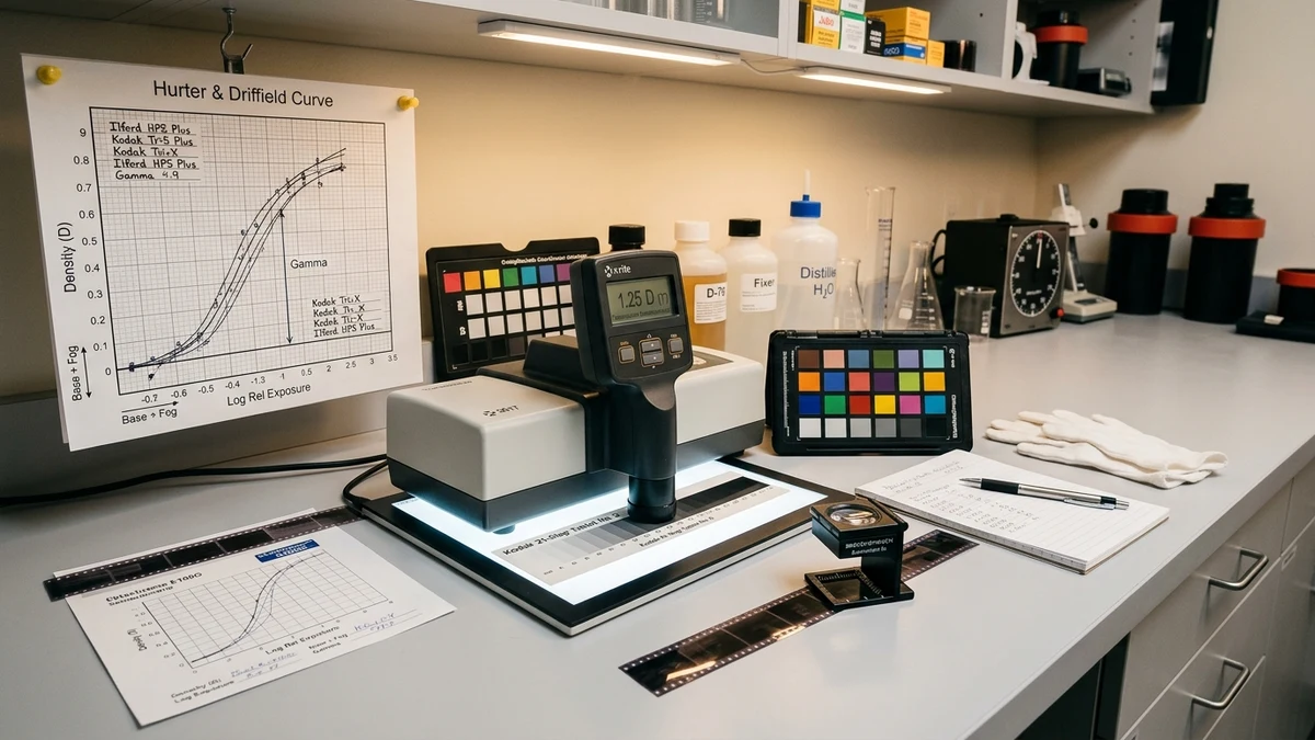
Photographic emulsions do not respond linearly to exposure; their sensitometric behavior follows an S-shaped Hurter & Driffield curve featuring a toe, a linear straight-line region, and a shoulder.
To reproduce the authentic aesthetic of photographic darkroom prints on paper, our shader applies a generalized logistic sigmoid transfer function:
S(x) = 1 / (1 + e-k(x - x0)) Where k corresponds to the user-adjustable contrast factor and x0 governs the midtone inflection point (determined by the exposure compensation value). This smooths deep shadows into natural rich blacks and rolls off bright highlights gently without harsh digital clipping.
4. Anti-Moiré Display Defocus Formulation
When using an electronic display as a light table, the film plane must be physically displaced from the display surface to blur discrete subpixels below the optical resolution of the camera sensor.
Given camera sensor pixel pitch psensor, camera lens focal length f, display pixel pitch pdisplay, and aperture N, the minimum elevation distance h required to expand a subpixel into a circle of confusion larger than the spatial period is calculated as:
h ≥ max(15 mm, (N × pdisplay × dmacro) / csensor) Our in-browser Anti-Moiré Calculator computes this threshold in real time based on your specific tablet, laptop, or monitor specifications.